3 phase air compressor pressure switch wiring diagram pdf
A 3-phase air compressor pressure switch wiring diagram is an essential guide for understanding the electrical connections and components of industrial air compressors. It provides detailed instructions for installing, testing, and troubleshooting the system, ensuring safe operation, efficiency, and preventing potential damage to the compressor and motor.
1.1 Overview of 3-Phase Power Systems
A 3-phase power system is commonly used in industrial settings due to its higher power efficiency and ability to handle heavier loads. It consists of three AC power lines with equal voltage and a 120-degree phase difference. This configuration reduces voltage drop and improves motor performance, making it ideal for powering air compressors and other heavy machinery. Understanding this system is crucial for proper wiring and operation.
1.2 Importance of Pressure Switches in Air Compressors
Pressure switches are vital for controlling the operation of air compressors, ensuring safe and efficient performance. They monitor tank pressure and automatically start or stop the compressor when preset levels are reached, preventing over-pressurization and motor damage. These switches also protect against rapid cycling, reducing mechanical stress and prolonging equipment lifespan. Proper installation, as detailed in the wiring diagram, ensures reliable operation and energy efficiency in industrial and commercial applications.

Understanding the Components of a 3-Phase Air Compressor
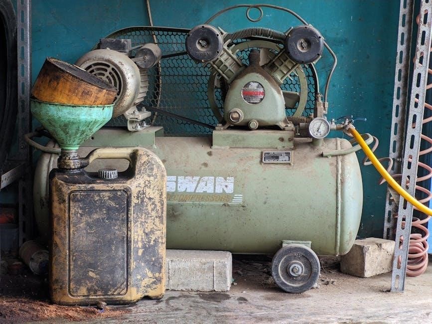
A 3-phase air compressor comprises a pressure switch, motor, and power supply. These components work together to regulate air pressure, ensuring efficient and safe operation.
2.1 Pressure Switch: Function and Design
A pressure switch in a 3-phase air compressor is designed to regulate air pressure by controlling the compressor’s on/off function. It features clearly marked terminals for power input and output, ensuring safe and efficient operation. The switch monitors pressure levels, shutting off the compressor when preset limits are reached. Its robust design includes electrical contacts and a mechanism to detect pressure changes, making it a critical component for system safety and performance.
2.2 Motor and Power Supply in 3-Phase Systems
In a 3-phase air compressor system, the motor is a key component, powered by three live wires (R, S, T) and a neutral wire (N). The power supply must match the motor’s voltage and frequency ratings for optimal performance. Proper wiring and connections are crucial to prevent damage and ensure efficient compressor operation. Compliance with National Electric Code (NEC) standards is essential for safety and reliability.

Wiring Diagrams for 3-Phase Air Compressor Pressure Switches
A 3-phase air compressor pressure switch wiring diagram guides the installation and troubleshooting of electrical connections between the pressure switch, motor, and power supply, ensuring correct setup.
3.1 What a Wiring Diagram Entails
A wiring diagram for a 3-phase air compressor pressure switch includes detailed visual representations of components such as the pressure switch, motor, and power supply. It outlines the connections between these parts, showcasing electrical circuits, control sequences, and safety measures. The diagram uses standardized symbols to depict wires, terminals, and switches, ensuring clarity for technicians during installation, troubleshooting, and maintenance. This essential tool helps prevent errors and ensures system efficiency and safety.
3.2 Key Symbols and Representations
A wiring diagram uses standardized symbols to represent components like the pressure switch, motor, and power supply. Symbols for wires, terminals, and switches are included, along with control sequences and safety features. These representations ensure clarity, allowing technicians to understand connections and electrical flows. Common symbols include circles for switches, rectangles for motors, and lines for wires, making the diagram a clear guide for installation, troubleshooting, and maintenance of the system.
Safety Precautions for Handling Electrical Components
Always disconnect power before working on electrical components. Ensure the compressor is off and unplugged. Avoid touching live circuits and use proper tools to prevent electrical shocks.
4.1 Essential Safety Measures Before Starting Work
Before handling electrical components, ensure the compressor is switched off and unplugged from the power source. Verify that all components are de-energized using a voltage tester. Wear appropriate personal protective equipment, including insulated gloves and safety glasses. Ensure proper ventilation to avoid inhaling dust or debris. Familiarize yourself with the wiring diagram and manufacturer’s instructions to prevent errors during installation or repairs. Never bypass safety devices or ignore warning signs, as this could lead to electrical hazards or system damage.
4.2 Identifying and Using Proper Tools
Use a multimeter to verify voltage and ensure components are de-energized. Insulated screwdrivers and pliers prevent electrical shocks. Wire strippers are essential for preparing connections. A voltage tester confirms power absence. Consult the wiring diagram to identify terminals and connections. Always follow manufacturer guidelines for tool usage to avoid damage to the pressure switch or motor. Proper tools ensure safe and efficient installation or repair of the 3-phase air compressor system.

Step-by-Step Installation Guide
Follow the wiring diagram to prepare components, connect the pressure switch, and integrate the motor and power supply safely. Ensure all connections are secure and meet electrical standards.
5.1 Preparing the Components
Begin by disconnecting the power supply and ensuring the compressor is turned off. Identify and prepare all components, including the pressure switch, motor, and power supply. Verify the wiring diagram to understand connections. Check terminals on the pressure switch for proper labeling, such as normally open or closed contacts. Ensure all wires and connectors are secure and insulated to prevent electrical hazards during installation.
5.2 Connecting the Pressure Switch
Start by disconnecting the power supply and ensuring the compressor is turned off. Locate the pressure switch terminals, typically labeled for input and output connections. Connect the power supply lines to the designated input terminals and link the motor to the output terminals. Refer to the wiring diagram to ensure correct connections. Double-check all wires to avoid mismatches and secure them tightly to prevent electrical issues during operation.
5.3 Integrating the Motor and Power Supply
Begin by aligning the motor terminals with the power supply phases, ensuring compatibility between the motor’s voltage rating and the power source. Refer to the wiring diagram to connect the three-phase wires accurately. Securely fasten each wire to the appropriate terminal, following the diagram’s guidance for phase sequencing. Install thermal overload protection and ensure proper grounding for safety. Verify the connections against local electrical codes and test the system to confirm smooth operation.
Troubleshooting Common Issues
Common issues include wiring faults, misaligned phase connections, and incorrect pressure settings; Verify the wiring diagram for proper connections and ensure the pressure switch is calibrated correctly. Check for loose wires, blown fuses, or tripped circuit breakers. If the compressor fails to start, inspect the motor terminals and power supply for compatibility with the wiring diagram specifications. Addressing these issues promptly prevents system damage and ensures reliable operation.
6.1 Identifying Faults in the Wiring
Identifying faults in the wiring of a 3-phase air compressor pressure switch involves checking for loose connections, misaligned phase wires, or blown fuses. Use a multimeter to verify voltage across terminals and ensure proper continuity. Check the wiring diagram for accurate connections between the pressure switch, motor, and power supply. Look for signs of overheating or arcing, which indicate short circuits. Correcting these issues ensures the compressor operates safely and efficiently, preventing motor damage or system failure.
6.2 Common Problems and Solutions
Common issues with 3-phase air compressor pressure switches include improper wiring, misconfigured settings, or worn-out components. Solutions involve checking the wiring diagram for accurate connections, adjusting pressure settings, and replacing faulty parts. Regular inspections prevent malfunctions, ensuring the compressor operates within safe pressure limits and maintains efficiency. Always refer to the diagram for troubleshooting and follow safety guidelines to avoid electrical hazards or system downtime.

Advanced Wiring Configurations
Advanced configurations like star-delta starters and soft starters optimize motor control, reducing voltage spikes and wear. These setups ensure smoother operation and enhanced protection for 3-phase compressors.
7.1 Star-Delta Starter Configuration
A star-delta starter is used in 3-phase systems to reduce voltage during motor startup, minimizing current spikes. The motor is initially connected in a star configuration, lowering the voltage, and then switched to delta for full operation. This method is ideal for 3-phase air compressors, as it ensures smooth starting and protects the motor from overload. The wiring involves specific terminals for the star and delta connections, ensuring a seamless transition between configurations.
7.2 Soft Starter Configurations
A soft starter configuration for 3-phase air compressors provides a gradual increase in voltage during startup, reducing current surges and mechanical stress on the motor. This configuration is ideal for systems requiring smooth acceleration and deceleration. Soft starters are programmable, allowing customization of startup and shutdown parameters. They enhance motor protection, reduce wear on components, and improve overall system efficiency. The wiring involves specific connections to ensure seamless integration with the pressure switch and motor controls.

Maintenance and Upkeep of the System
Regular inspections and cleaning of the pressure switch and wiring are essential to ensure optimal performance. Check connections and replace worn components promptly to avoid downtime and ensure safety.
8.1 Regular Checks and Inspections
Regular checks and inspections are crucial for maintaining the efficiency and safety of a 3-phase air compressor system. Ensure the pressure switch is calibrated correctly and free from debris. Inspect the wiring connections for any signs of wear or damage. Check the motor and power supply for proper function and alignment with the wiring diagram. Clean or replace components as needed to prevent malfunctions and ensure smooth operation.
8.2 Replacing Worn-Out Components
Replacing worn-out components in a 3-phase air compressor system is essential for maintaining efficiency and safety. Regularly inspect the pressure switch, contacts, and wiring for wear. When replacing, ensure the new components match the specifications in the wiring diagram. Disconnect power before starting work, and follow proper installation procedures to avoid damage or malfunction. Always consult the manufacturer’s manual for specific guidance on replacement and compatibility.

Compliance with Electrical Standards
Ensuring compliance with electrical standards is crucial for safe and efficient 3-phase air compressor installations. Adhere to National Electric Code (NEC) and local regulations to avoid hazards and legal issues.
9.1 National Electric Code (NEC) Compliance
Adhering to the National Electric Code (NEC) ensures the safe installation and operation of 3-phase air compressor systems. The wiring diagram must comply with NEC standards for voltage, phase, and wire sizing. Proper grounding, overload protection, and disconnect switches are essential. Regular inspections and adherence to NEC guidelines help prevent electrical hazards and ensure system efficiency. Always consult local regulations to supplement NEC requirements for comprehensive compliance.
9.2 Local and International Regulations
Beyond NEC, 3-phase air compressor systems must comply with local and international regulations, such as those outlined by the International Electrotechnical Commission (IEC). These standards ensure safety, efficiency, and environmental compliance. Proper documentation and certification are often required. Always consult local authorities and use certified components to avoid penalties and ensure adherence to both domestic and global electrical codes, fostering a safe and reliable installation process worldwide.

Tips for Creating a DIY Wiring Diagram
Use symbols and clear labels to represent components like the pressure switch and motor. Ensure the diagram reflects the actual wiring setup for accuracy. Always include a legend for easy interpretation.
Reference manufacturer guides and safety standards like NEC to ensure compliance. Use software or templates to create a neat, organized layout that enhances readability and understanding of the circuit.
10.1 Tools and Software Needed
To create an accurate wiring diagram, you’ll need tools like a multimeter, wire strippers, and a soldering iron. For software, use AutoCAD, Fritzing, or Lucidchart to design the diagram. Ensure your tools are compatible with 3-phase systems and always follow safety guidelines when handling electrical components. Free tools like Draw.io can also help in creating clear, professional diagrams for your air compressor setup.
10.2 Best Practices for Diagram Clarity
Use standard symbols for components like the pressure switch and motor to ensure consistency. Color-code wires to differentiate between phase lines, neutral, and ground. Clearly label each component and connection point to avoid confusion. Include a legend to explain symbols and ensure an organized, logical layout. Avoid overcrowding and cross-reference with the user manual for accuracy. This will make the diagram easy to follow and understand.
A properly wired 3-phase air compressor pressure switch ensures safe, efficient operation. Always follow the wiring diagram and safety guidelines for optimal performance and compliance with electrical standards.
11.1 Summary of Key Points
The 3-phase air compressor pressure switch wiring diagram is crucial for ensuring safe and efficient operation. Key points include understanding the wiring diagram, identifying terminals, and connecting components correctly. Always switch off the compressor and unplug it before working. Ensure compatibility between the motor rating and power supply. Follow safety guidelines and electrical standards like NEC for proper installation and troubleshooting. Regular maintenance and inspections are essential to prevent issues and extend system lifespan.
11.2 Final Thoughts on Safe and Efficient Installation
Safe and efficient installation of a 3-phase air compressor pressure switch requires meticulous attention to detail. Always disconnect power before starting work and use proper tools. Refer to the wiring diagram and follow electrical standards like NEC. Regular inspections and maintenance ensure optimal performance and prevent unexpected failures. By adhering to these guidelines, you can achieve a reliable and long-lasting installation for your air compressor system.

Additional Resources
For further guidance, refer to official wiring diagram PDFs, manufacturer guides, and online forums discussing 3-phase air compressors. These resources offer detailed troubleshooting and installation tips.
12.1 Recommended Reading and References
Official manufacturer guides and technical manuals provide comprehensive details on 3-phase air compressor systems. The “compressorselectricale-205126 rev 6” PDF and “Baset Series Air Conditioner with Puron r” documentation are highly recommended. These resources ensure compliance with National Electric Code (NEC) standards and offer practical wiring insights. Additionally, online forums and tutorials offer hands-on tips for installers and technicians.
12.2 Online Communities and Forums
Online forums like Reddit and specialized electrical engineering communities offer valuable insights and discussions on 3-phase air compressor systems. These platforms provide real-world experiences, troubleshooting tips, and practical advice from professionals. Joining these communities can help resolve complex wiring issues and gain deeper understanding of system maintenance through shared knowledge and expertise.
Get the 3 phase air compressor pressure switch wiring diagram PDF for easy installation and troubleshooting. Download now!